
Evaporator Woes – Vacuum Control, Velocity, and Carryover
- Posted on 25th September 2020
- in Articles, Falling Film Evaporators, Other
- by John Real
 Recently, we have been working with a client to reduce carryover in their legacy rising film evaporator for dairy products. To see a working rising film evaporator is an absolute treat. This was the first one I had ever seen in person on a dairy application. It was awesome.
This two-stage, Thermal Vapor Recompression (TVR) driven evaporator was fouling their cooling tower fill immediately after it was replaced whenever they would perform their annual maintenance on the tower. They were getting a lot of carryover from the separator into the barometric condenser and into the cooling tower and could not figure out why. After talking to the operators for a bit, they mentioned that immediately after they replaced the cooling tower fill, the vacuum on the evaporator would be great, better than they can normally ever achieve, but that over time as the tower fill was fouling it would gradually trackback to normal operation point and that the carryover would stop.
Most of the evaporators we run into are vacuum-based systems – either in dairy or on other food products in general. Evaporators that run under a vacuum do so to protect the product from damage – especially the proteins. Proteins are very susceptible to damage by heat. Think about boiling milk on your stovetop – if you are not careful to do it over low heat stirring constantly, you will end up with a hard brown scale on the bottom of your pan and burnt tasting milk. We certainly do not want to buy burned condensed milk in the grocery store or have off tasting bread because the milk powder was brown.
By evaporating, or boiling, the milk under a vacuum we can remove the water without damaging the proteins and giving it that brown, burnt taste. It also helps keep the evaporator running longer as we do not foul the tubes as quickly.
So, if some vacuum is good, more vacuum is better right? I mean, the more vacuum we have, the colder we can run the product, so we will protect it even more, and maybe get very little to no fouling?
Unfortunately, not quite. The further down in vacuum we get the more difficult it can be to maintain that vacuum and even small vacuum leaks will have a higher and higher impact. When designing an evaporator system, we must ensure that we can get the boiling vapors out of the system. Typically, this is performed by a vapor separator followed by vapor ducting to route the vapors into either the next effect if a multi-effect evaporator or the condenser. There are many different designs of vapor separators used on evaporators and everyone has their favorites, but the name of the game in separator and duct design is pressure drop and vapor velocity.
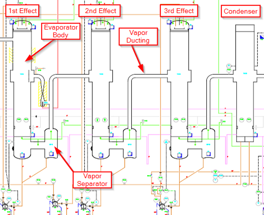
Figure 1. Three Effect TVR Driven Evaporator Schematic Example
Let’s assume this three-effect TVR driven evaporator is designed for an evaporation rate of 8,000 pounds of water evaporation per hour. In this case, each effect will be responsible for 2,000 lbs per hour of evaporation with the TVR responsible for another 2,000 lb/h of evaporation. We have decided that the design point of our final, deepest vacuum, and coldest effect, the effect that will drive the vacuum levels of the other two effects, will be 2.5 psi(a) or about 24.8 inHg. Based on this level of vacuum and our expected 2,000 lb/h of evaporation from this effect, we decide that we will size the vapor ducting at 1 foot or 12 inches. This gives us a vapor velocity of 100 ft/s and is the maximum we would design for. At 9 inches (0.75 ft) we are at 180 ft/s, which is a little too high.
However, what happens if we can get a better vacuum? What is really the worst that can happen? It is time to break out our steam tables!
As the vacuum increases or the pressure decreases, we get an increase in the specific volume of the vapors. The specific volume is the amount of space, in this case in cubic feet, that a given mass, in this one pound-mass, of vapor takes up. As we decrease the pressure, we increase the specific volume. This makes sense from a physics point of view because as we decrease the pressure, the gas molecules have less resistance to movement and spread out further and further.
The rate of increase in specific volume as the vacuum increases is pretty mild. However, as we get closer to perfect vacuum, the specific volume suddenly increases dramatically.
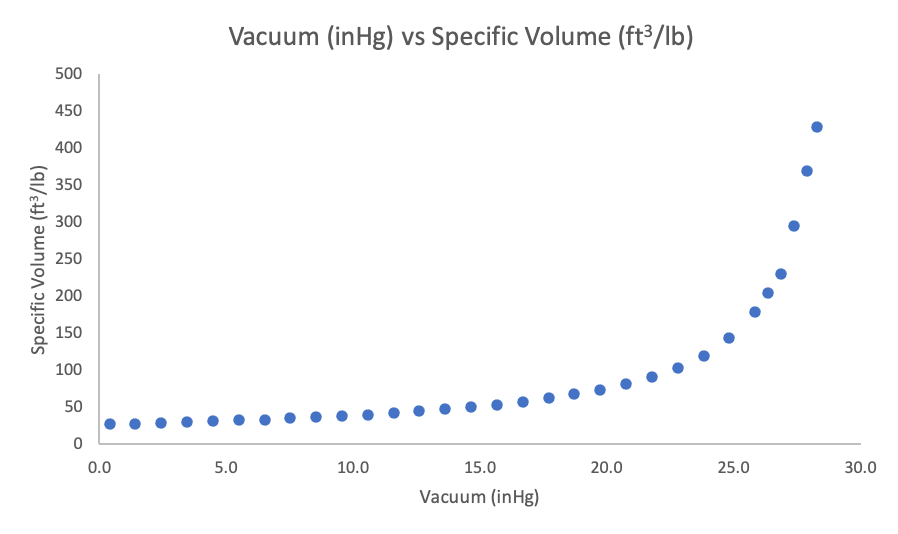
Figure 2. Vacuum Level (inHg) vs Specific Volume of Steam (ft3/lb)
When increasing the vacuum from atmosphere (0 inHg) to 5 inHg, the specific volume increases by 5 ft3/lb. However, when increasing the vacuum from 23 inHg to 28 inHg the specific volume increases by 310 ft3/lb.
In our TVR evaporator example, at 24.8 inHg (2.5 psia), we have a specific volume of about 143 ft3/lb. It is this vapor volume that our vapor duct is sized for. However, if we achieve a higher vacuum – say 1.5 psia (26.9 inHg) – our specific vapor volume almost doubles and increases to 230 ft3/lb. This means we are suddenly trying to squeeze twice the volume through the same size duct. Since we cannot increase the size of the ductwork, the vapor must speed up. In this example, our vapor velocity increases from 100 ft/s to 162 ft/s. Given the same mass flow and cross-sectional area, the increase in velocity will follow the same curve as the change in specific volume.
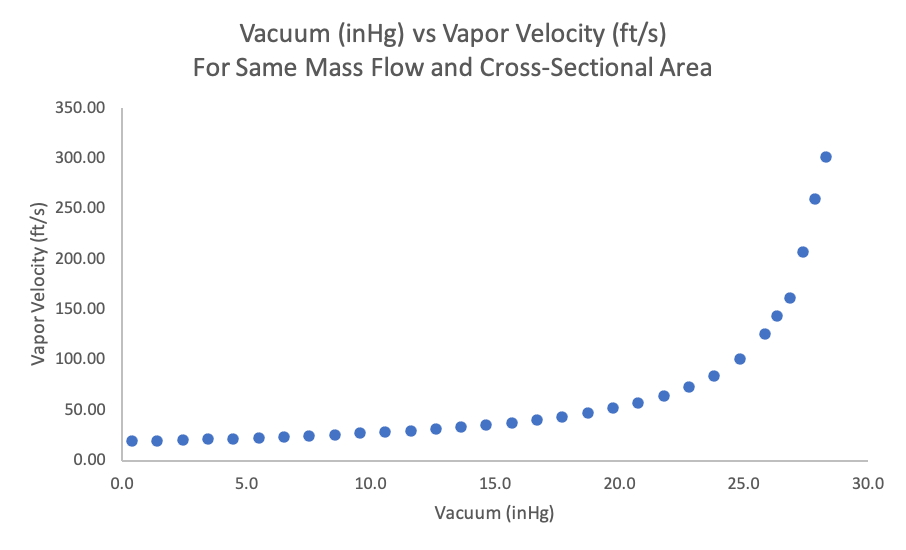
Figure 3. Vacuum (inHg) vs Vapor Velocity of Mass Flow and Cross-Sectional Area
As we increase the velocity, we also have the chance of increasing carryover of product droplets out of the separator. The separators work through both impact of the drops on the internal surfaces of the vessel and through velocity disengagement of product droplets. If we increase the velocity, we no longer have the velocity disengagement of particles – the speed of the vapors keeps the droplets entrained. In addition, if the separator works on cyclonic action, we may pick up more product by causing a motion like a tornado in the center of the separator.
For rising film evaporator client, the annual fill replacement on the cooling tower resulted in much colder cooling water being fed into the direct contact condenser. As a result, while normally operating around 23.2 to 24.2 inHg in vacuum, replacing the fill they were able to reach vacuums of 27 inHg or more. This resulted in a doubling of their vapor volumes which was pulling product into the barometric condenser. As barometric condensers are direct contact – the cooling water is directly in contact with the water vapors from the evaporators – this product was entering the cooling water stream. It was transported to the cooling towers where it began to foul the cooling tower fill. The cooling tower continued to foul, decreasing the effectiveness of the cooling tower, and reducing the ability of the condenser to condenser the evaporator vapors.
This process continued until the vacuum decreased to a point that the system no longer pulled product vapors into the condenser and therefore into the cooling tower. The solution to this issue is relatively straight forward – vacuum control. In this case, a modulating control valve to bleed air into the system to control the vacuum of the evaporator solved this problem. With a pressure transmitter and this valve, we are able to bleed air into the system, maintaining the vacuum level where we want it after the cooling tower fill is replaced and preventing the carryover and fouling and reducing the frequency of cleanings required on the cooling tower.

In addition, he leads a team of engineers and designers to assure efficient and timely delivery of process engineering, equipment, system changes, and optimization efforts to help our customers get the most out of their capital investments.
- Evaporator Woes – Vacuum Control, Velocity, and Carryover - September 25, 2020
- Dryer Safety – Explosion Protection - April 20, 2019
- Direct vs Indirect Fired Heaters for Spray Dryers - January 14, 2019